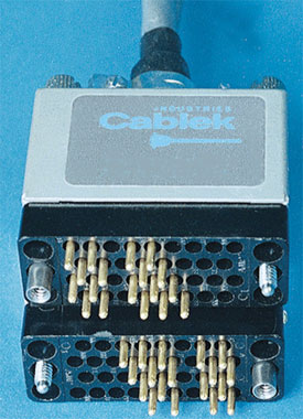
V.35 Cable Assemblies
Internal Reference :Description :
V.35 CUSTOM
Internal Reference:
V.35 CUSTOM
Ces câbles sont fabriqués sur mesure, selon vos dessins et spécifications.
Envoyez-nous votre demande par courriel
V.35 Interface Cables V35 Cables
Cablek Industries manufactures a wide variety of cables for the CCITT V.35 interface.
These are custom made cables. Cablek stocks all the necessary components to manufacture any configurations and lengths.
Email us with your requirements.
V.35 is the interface standard used by most routers and DSUs that connect to T-1 carriers.
V.35 (V35) Cables are high-speed serial assemblies designed to support both higher data rates and connectivity between DTE's (Data Terminal Equipment) or DCE's (Data Communication Equipment) over digital lines.
Although V.35 (V35) is commonly used to support speeds ranging anywhere from 48 to 64 Kbps, much higher rates are possible [ ISDN (64 or 128Kbps), Factional T1@ 128 Kbps to 1.544Mbps T1, ATM and Frame Relay].
V.35 (V35) cable distances theoretically can range up to 4000 feet (1200 m) at speeds up to 100 Kbps. Actual distances will depend on your equipment and the quality of the cable.
To achieve such high speeds and great distances, V.35 (V35) combines both balanced and unbalanced voltage signals on the same interface. Transmission is usually a synchronous protocol (note clocking pins i.e. receive and transmit clock).
 |
V.35 Male
V.35 Female
|
DTE to DCE
(All differential pairs must be twisted)
DTE DCE
P ------------------- P
S ------------------- S
R ------------------- R
T ------------------- R
C ------------------- C
D ------------------- D
E ------------------- E
H ------------------- H
Y ------------------- Y
AA ---------------- AA
V ------------------- Y
X ------------------- X
DTE to DTE
This cable design assumes that both devices provide their own transmit clock. Not all equipment does, in which case a modem eliminator with clock will be needed. If only one device has a clock you might be able to get away with using the one clock to drive transmit and receive in both devices.
DTE DTE
P ---------------------- R
S ---------------------- T
R ---------------------- P
T ---------------------- S
C ---------------------- D
D ---------------------- C
E ---------------------- H
H ---------------------- E
Y & U ----------------- V
W & AA -------------- X
V ------------------ Y & U
X ----------------- W & AA


